Model: BIG EYE B-36
Maximum Cutting Length: 36" (914mm)
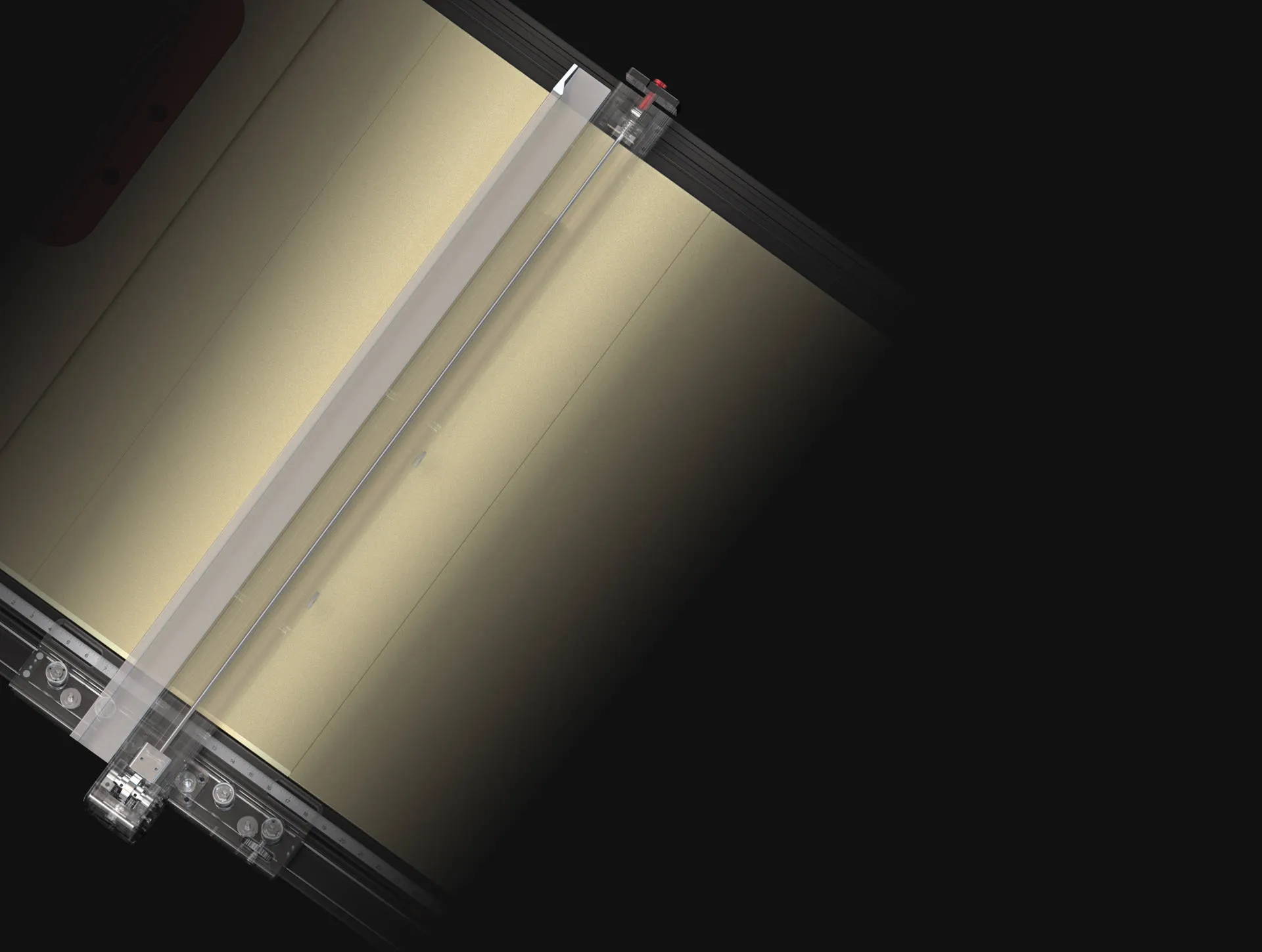
Front Guide Rail Dimensions: 69-1/4" x 3-5/8" (1760 x 92mm)
Rear Guide Rail Dimensions: 59-5/8" x 2-9/16" (1515 x 65.5mm)
Fence Overall Length: 41-3/8" (1050mm)
Maximum Load Capacity: 300N
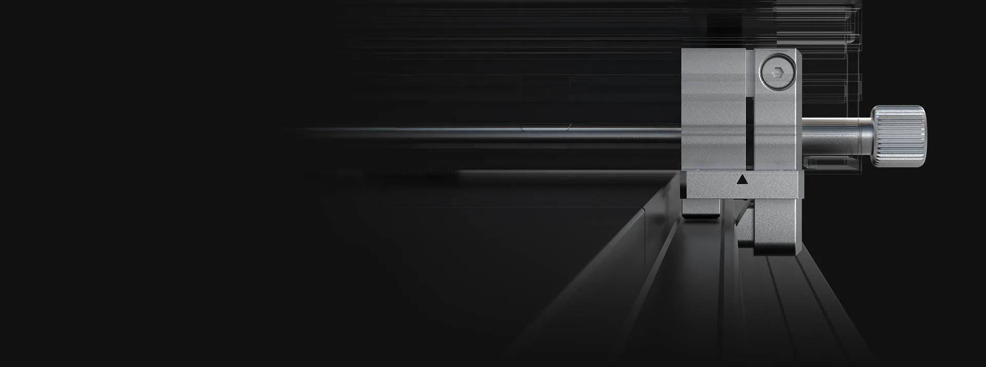
Movement Accuracy: 0.15mm (0.006") throughout full length
Locked Position Accuracy: 0.02mm (0.0008")
Scale Resolution (Imperial): 1/32"
Scale Resolution (Metric): 1mm
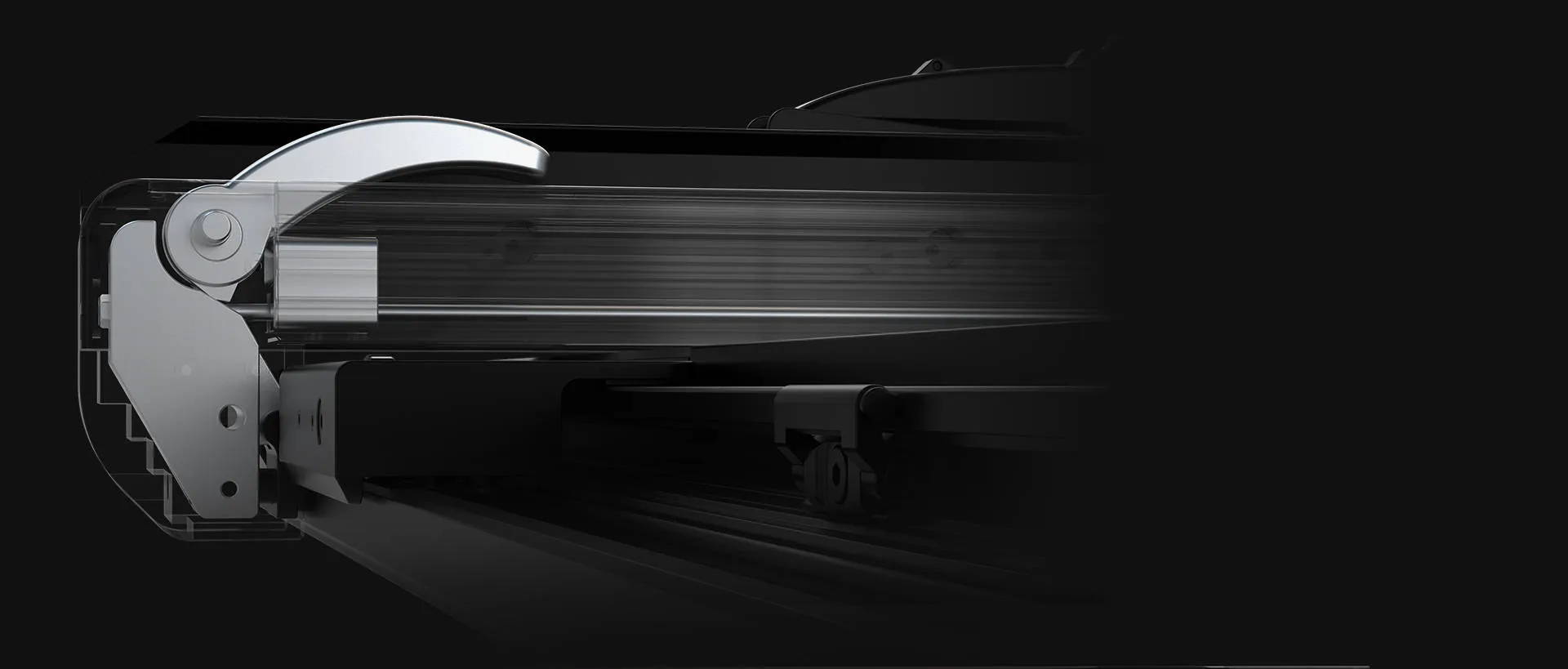
Number of Flip Position Stops: 4
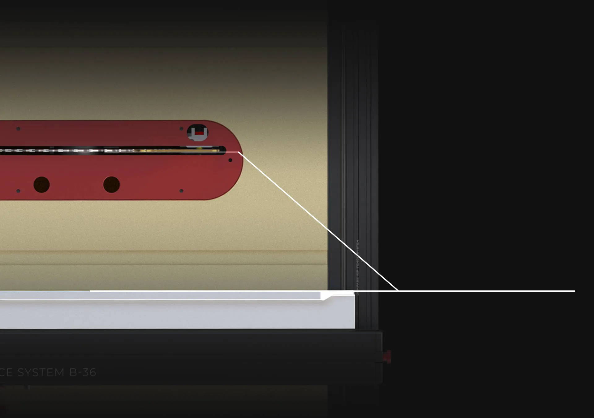
Viewing Window Material: K9 Crystal Glass (92% light transmittance)
Net Weight: 62 lbs (28kg)
Gross Weight: 73 lbs (33kg)
Package 1 Dimensions: 71-47/64" x 7" x 4-17/32" (1822 x 178 x 115mm)
Package 2 Dimensions: 43-25/32" x 16-15/16" x 6-29/32" (1112 x 430 x 175mm)
Compatible Table Width: 685-800mm (27-31.5")
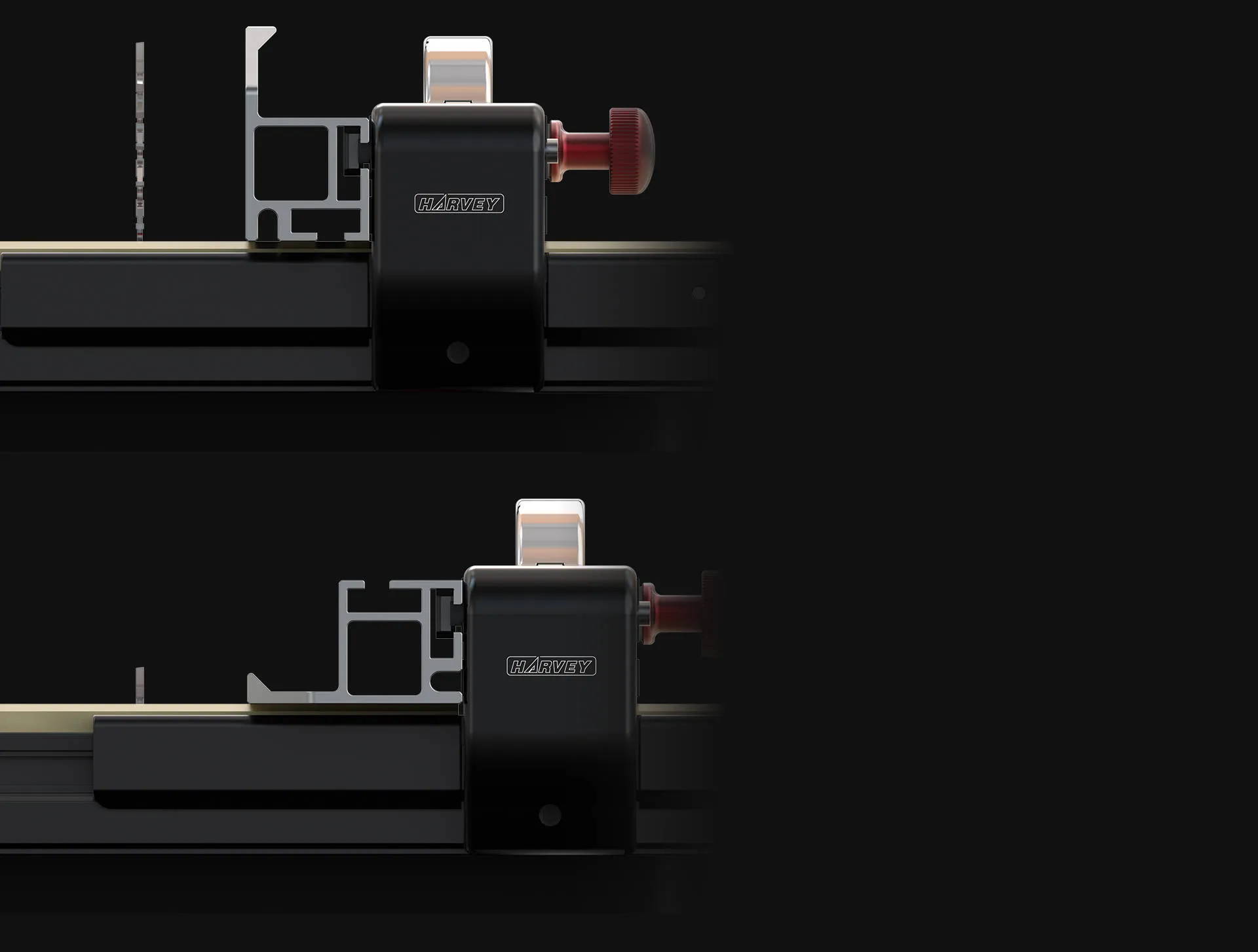
Guide Rail Mounting Height: 26-29mm from tabletop
Mounting Hole Size: 8-12mm diameter
T-Slot Depth Requirement: ≤10mm


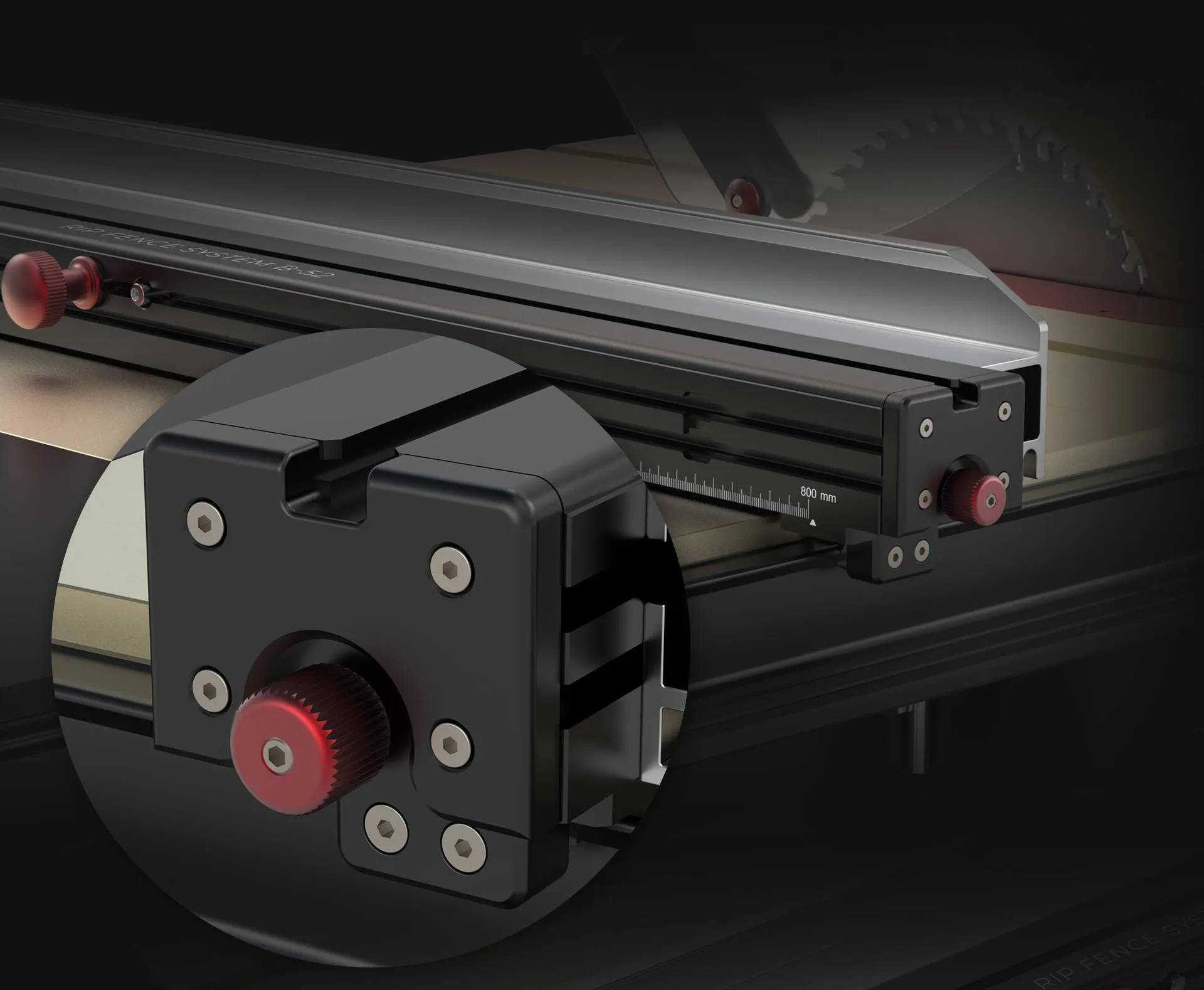


 to 800mm (31-½ inches)")